Send an enquiryEmail: available through the contact form

Subject foundations

Bioelectricity, measurement and impedance: the foundations

Clear explanations of the physical and measurement concepts behind bioelectrical impedance analysis and related research. Established principles come first; the limits of interpretation follow each section.

Section 1

Introduction to bioelectricity

What is bioelectricity?

Bioelectricity is electrical activity generated by living tissue, mainly through the movement of ions across cell membranes.

Ions such as sodium, potassium, calcium and chloride are unevenly distributed across the membrane. Their movement creates potential differences and currents. Familiar clinical examples include the electrocardiogram (ECG), electroencephalogram (EEG) and electromyogram (EMG).

How is bioelectricity different from bioimpedance?

Bioelectricity is generated by the tissue. Bioimpedance is the passive opposition of tissue to a current applied from outside.

Both are measured with electrodes and both involve ionic conduction, but they answer different questions. A standard BIA device applies an external current and measures the response, so it does not record the tissue's own signals.

Key idea. Active bioelectric signals are produced by tissue. Impedance measurements apply a small external signal and record the passive response.

Section 2

Basic physiological measurements

What is a physiological measurement?

A physiological measurement is a quantitative record of a biological function or structure, made with a defined method, unit and set of conditions.

Every measurement has a method, a unit and an uncertainty. A reading is only useful if it is valid (it measures what it claims to measure) and reliable (repeated readings agree within known limits).

Examples of common physiological measurements (general information)
MeasurementWhat it recordsKey considerations
Electrocardiogram (ECG)Electrical potentials generated by the heart, recorded with surface electrodesElectrode placement, skin contact, interference and standard lead configurations
Electromyogram (EMG)Electrical activity of skeletal muscleElectrode type, muscle activity state and movement artefacts
Blood pressurePressure in the arterial system, measured by cuff or invasive methodsCuff size, posture, rest period and device validation
Body temperatureCore or surface temperature, depending on the site and methodSite, timing and ambient conditions
Bioelectrical impedanceResponse of a body segment or the whole body to a small applied alternating currentHydration, temperature, posture, electrode placement and device model
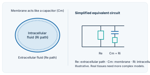
Schematic of a cell with intracellular and extracellular fluid, and a simplified equivalent circuit with an extracellular resistor in parallel with a membrane capacitor in series with an intracellular resistor.
Illustrative simplified model. Real tissues are more complex than this circuit. It shows why impedance depends on frequency.
Section 3

Electrical properties of biological tissues

Why does tissue impedance change with frequency?

Tissues conduct current through ionic solutions, and cell membranes act as capacitors. Their combined response changes with the frequency of the applied current.

In simplified textbook models, low-frequency current flows mainly through the extracellular fluid, because the membrane acts as an insulator. At higher frequencies the membrane's capacitive path becomes more conductive, so current also passes through cells. The impedance therefore varies with frequency.

This is a simplified picture. Real tissues contain many compartments, and the models used to interpret measurements are approximations.

Section 4

Resistance, reactance and impedance

What is the difference between resistance and reactance?

Resistance dissipates energy and is in phase with the voltage. Reactance stores and returns energy and shifts the phase of the current relative to the voltage.

Resistance (R) arises from ionic conduction. Reactance (X) arises from capacitive (and, in other systems, inductive) elements. For an ideal capacitor, the reactance magnitude is Xc = 1 / (2πfC), so it falls as frequency increases.

How are they combined?

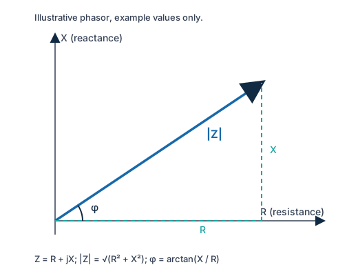
Impedance is the complex sum of resistance and reactance: Z = R + jX.

The magnitude is |Z| = √(R² + X²), and the phase angle is φ = arctan(X / R). By convention capacitive reactance is negative, although many device reports quote its magnitude, so sign conventions should always be stated.

Right-angled phasor diagram: resistance R on the horizontal axis, reactance X on the vertical axis, impedance vector Z between them, and phase angle phi at the origin.
Illustrative phasor, example values only. R is horizontal, X is vertical, and the impedance vector Z is their sum.
Section 5

Biomedical instrumentation

What does a biomedical measurement system do?

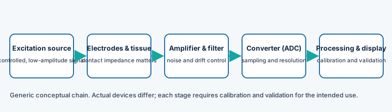
It produces a controlled stimulus or records a physiological signal, converts it into digital data, and processes and displays the result. Each stage can add error, so each must be calibrated and validated.

Block diagram of a generic measurement chain: excitation source, electrodes and tissue, amplifier and filter, analogue-to-digital converter, and processing and display.
Generic conceptual chain. Actual devices differ in design. Electrical safety of medical equipment is covered by standards such as the IEC 60601 series.
  • Excitation or sensing: a controlled, safe and well-characterised signal, or a calibrated sensor.
  • Electrodes and contact: skin preparation, electrode type and placement strongly affect the result.
  • Signal conditioning: amplification, filtering and noise control.
  • Conversion and processing: sampling rate, resolution and the algorithms used to compute derived values.
  • Calibration and validation: checks against reference standards and known test loads.
Section 6

Measurement accuracy and reproducibility

How is accuracy different from reproducibility?

Accuracy describes closeness to a true or accepted reference value. Reproducibility describes how consistently a measurement gives the same result under stated conditions.

A device can be reproducible but inaccurate, and an accurate device can still be poorly reproduced if the procedure varies. Both must be assessed.

How should reproducibility be quantified?

Repeatability is tested with repeated measurements under the same conditions. Reproducibility is tested across operators, devices, sites or times.

Common approaches include the coefficient of variation, intraclass correlation coefficients and Bland–Altman analysis of agreement. These should be reported before a difference between two measurements is interpreted.

Practical checklist

  • State the device, model, software version and frequency used.
  • Standardise and record the measurement conditions.
  • Calibrate or check the device against a reference.
  • Measure repeatability in the study population before use.
  • Report agreement statistics, not only mean values.
Section 7

Research methodology and limitations

This section is important for anyone reading measurement studies in homoeo-bio-engineering.

Can a change in a measurement show that a treatment works?

Not by itself. A change in a measured value is one piece of information. It must be interpreted within a study design that can separate treatment effects from other causes.

Several things can change a measured value without any treatment effect. These include hydration, time of day, recent food or exercise, skin temperature, electrode position, the measurement device, and the expectations of participants and observers. Study design is the main protection against these explanations.

Design features that support interpretation

  • A written, pre-specified protocol and ethics approval before recruitment.
  • A comparison or control group, with allocation method described.
  • Blinding of participants or assessors where feasible.
  • Standardised measurement conditions and documented confounders.
  • Pre-specified outcomes and an agreed statistical analysis plan.

Reporting and limitations

  • Report negative and inconclusive results as well as positive ones.
  • Describe the limitations of the device, the method and the sample.
  • Follow relevant reporting guidelines, such as CONSORT for randomised trials and STROBE for observational studies.
  • Separate exploratory findings from confirmatory ones.
  • Do not present preliminary or animal results as clinical evidence.
Sources

References and further reading

Check editions and page numbers against the publisher or a library copy before citing.

  1. Grimnes S, Martinsen ØG. Bioimpedance and Bioelectricity Basics. Academic Press; 2015.
  2. Kyle UG, Bosaeus I, De Lorenzo AD, et al. Bioelectrical impedance analysis, part I: review of principles and methods. Clinical Nutrition. 2004;23(5):1226–1243.
  3. Webster JG, editor. Medical Instrumentation: Application and Design. Wiley (multiple editions).
  4. JCGM 200:2012. International vocabulary of metrology: Basic and general concepts and associated terms (VIM). BIPM.
  5. Bland JM, Altman DG. Statistical methods for assessing agreement between two methods of clinical measurement. Lancet. 1986;1(8476):307–310.
  6. Chan AW, Tetzlaff JM, Altman DG, et al. SPIRIT 2013 statement: defining standard protocol items for clinical trials. Annals of Internal Medicine. 2013;158(3):200–207.
  7. Schulz KF, Chalmers I, Hayes RJ, Altman DG. Empirical evidence of bias. JAMA. 1995;273(5):408–412.

Next: BIA and EIS guide · Glossary of terms